A Great proof of concept
I finished building the first Hall sensor array, and after not small amount of fiddling around, figured out how to install it into the manual. It works!
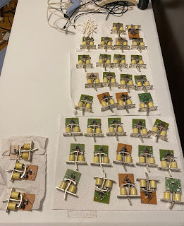
So, now to back up a bit and document what I did. I build the sensors into strips of 8 for ease of handling (and one short one of 5 because 61 keys)
I bought 160 Melexis US5881LUA-AAA-000-BU sensors from Mouser. With the front (beveled) part facing me, the left pin is power, center is ground, and the right is signal. I happened to have a roll of 1/4" copper foil tape so I figured I'd experiment with using it as ground and power bus, it doesn't take much room and can be soldered to. I put a strip on the front and back of a piece of flexible proto-board. The flexibility wasn't especially important here, but being able to cut it easily was .
The legs are a bit fragile, but I didn't break more than one or two before I got the hang of handling them. Bending them with pliers works better than fingers. I pulled the center leg back a bit and threaded it through a hole in the board letting the outside legs slide down across the foil tape.
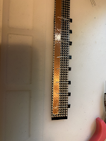

I clipped the right leg a little above the foil tape so it didn't contact power. Here I have a strip connected to the controller and I'm testing with a magnet


I did make a mistake I'm going to have to correct - when I drew the template to place the sensors on the proto board, I didn't pay enough attention to the variations in size of the keys. They look just alike at a glance, but if you look very close, some are narrower than others - the black keys are a bit thinner. The result is some of the sensors are too far over and I can't position their magnets correctly so I have some dead notes and some that cipher frequently. I'm taking what I learned and building the second set of sensors more carefully. I'll put the second set onto the Great manual, replacing the current one, then I can continue using it to play while I take the first one apart and fix it to install into the Swell manual.
Even with the wonky notes, I had a lovely afternoon playing with hands and feet together. I'm going to make good progress now with being able to practice more frequently without having to travel to church.
Updated to add - I forgot to mention with the controller change I completely changed the arduino sketch. The current version is so much simpler. I love deleting code.
https://github.com/lizny/OrganMIDIScanner/releases/tag/Beta_2
Next...
So, now to back up a bit and document what I did. I build the sensors into strips of 8 for ease of handling (and one short one of 5 because 61 keys)
I bought 160 Melexis US5881LUA-AAA-000-BU sensors from Mouser. With the front (beveled) part facing me, the left pin is power, center is ground, and the right is signal. I happened to have a roll of 1/4" copper foil tape so I figured I'd experiment with using it as ground and power bus, it doesn't take much room and can be soldered to. I put a strip on the front and back of a piece of flexible proto-board. The flexibility wasn't especially important here, but being able to cut it easily was .
The legs are a bit fragile, but I didn't break more than one or two before I got the hang of handling them. Bending them with pliers works better than fingers. I pulled the center leg back a bit and threaded it through a hole in the board letting the outside legs slide down across the foil tape.


I clipped the right leg a little above the foil tape so it didn't contact power. Here I have a strip connected to the controller and I'm testing with a magnet
With a working set of 8 sensors, I want to make sure I can position them so that the travel distance of the magnets on the keys is enough to register reliably. I've decided to place the sensors underneath rather than on top - there's a lot less mechanical stuff in the way here. This mean they sensors will be normally next to the magnet, and a keypress will move it away. I used magnetic attractive (ferrous) tape cut into strips and stuck to the bottoms of the keys at the far end. This lets me hang a magnet on each with some ability to wiggle it around to get in range of the sensor. I built a small tester using an 8 pixel strip from Adafruit I had around in my toybox. The lights are all lit showing the sensors are detecting the magnets. I could 'play' the keys and watch the lights flick on and off. Yay!

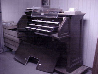
Here we have the whole set of sensors, taped down to a small wood board and wired up. I screwed on some hinges and tried rotating it into position, but the springs behind the keys were in the way.
I ended up cobbling together some wooden supports screwed to the wood box behind there. I didn't grab a photo before it went into the organ. It was pretty rough, just enough to turn it right way round and give it a real playtest

Even with the wonky notes, I had a lovely afternoon playing with hands and feet together. I'm going to make good progress now with being able to practice more frequently without having to travel to church.
Updated to add - I forgot to mention with the controller change I completely changed the arduino sketch. The current version is so much simpler. I love deleting code.
https://github.com/lizny/OrganMIDIScanner/releases/tag/Beta_2
Next...

Comments
Post a Comment