Pistons of Studliness
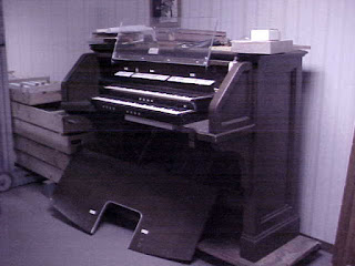
My organ console, as I received it, had 13 thumb pistons. It had been wired for 2 toe studs, but they were removed before it was sold to me.
The pistons had the same issue as all the other wiring, it really wanted to run at 12 volts, not 5. The toe studs are OSI standard buttons with copper contacts and worked just fine at 5 volts, so all that was going to be necessary was to install them and hook them to an arduino. I decided to do the toes first, and think about the thumbs while I worked on it.

Here are my gently used toe studs as they arrived. Half are on those oak rails, and half packed into that plastic bottle. They are machined from solid metal, so nothing can really happen to them in the mail, but nice not to be rattling around loose. Inside the medicine bottle I found the screws and label plates for the loose studs.

I was hoping i'd be able to use the rails - they have a nice rake to them, and it would simplify installation. I set out the front apron from my organ on a pair of sawhorses to try them out for fit. Hooray for standardization - the length and curve of both exactly matched the bottom of the board.

I made a paper template and marked where the wires needed to go, and where the screw-holes in the rail are, and drilled everything to fit.

And here we are all installed. I planned the placement of the upper row to match the curve of the bottom ones, including being a tiny bit turned in from the outside instead of parallel to the floor. I think it looks very nice. I polished them with vinegar and a soft cloth which did a nice job on the nickel finish.

Back inside, I flipped the board over and started wiring. Each stud came with 6" or so of wire attached, I ran a common bus with 1/4" copper tape - and apparently failed to get a photo. One of each pair of wires I soldered to the tape. The other I spliced to a long green wire. Over on the left - which is the right side of the organ with the panel installed - I screwed on a protoboard with 2 mcp23017 chips on it, and female header soldered to the inputs of of the chips. There are 17 toe studs in all, which annoyingly is just one more than will fit on a single chip - but they only cost about $3 so I'll just waste a few ports rather than make things complicated to save one chip.
I just inserted the ends of the wires into the header and fastened it all down moderately securely. I soldered the leads of a 4-pin JST connector to the proto-board, and made a cable with the other half of the connector. That cable goes onto the controller running the swell keyboard, I had put in female header for the 4 wires in advance. The keyboard uses 4 pin expander chips and had room on the bus for 4 more, so adding the pistons was just a matter of adjusting the programming.

Here they all are, shining in the light of my new pedal light - which is an led strip, with a small potentiometer for controlling brightness.
Next step is wire the thumb pistons. 13 of them will fit onto one more port expander chip, which I'll put on top of the swell to the left, there is a channel routed into the wood going that way already, from the original wiring.

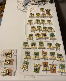
The pistons have the same issue as all the other original wiring, it isn't designed to run at 5 volts. You can see the oxidation on the wires and cleaning it will only help temporarily.
My original scheme for these was to remove all the wiring and contact springs and put in reed switches. I quickly found that there was not enough travel distance, I couldn't get the magnets far enough away from the switches for them to ever be open.

I tried putting a bit of copper foil across the bottom wire there. It was a big improvement, it sometimes worked, but not reliably enough to be the solution. Besides, I'd removed the original contact spring wires from a bunch of them and needed a replacement.

I picked up some piano wire, because it has the stiffness needed to not get bent out of shape by the piston action, and soldered it to the pin, along with a new 30 gauge wire. Instead of two contacts, I used more copper tape to make a ground bus and soldered a bit of wire leading to it - this is 30awg stranded with silicone insulation so is very soft and flexible and won't break with the button motion over time.
Possibly the piano wire will oxidize and I'll be back to my original problem, but we'll have to see over time.

I'm securing the wire bundle with some linen warp I have around. I put the wire ends onto a piece of header so can just plug into my controller board.

So nice to have these guys back in place!

Comments
Post a Comment