How Beautiful are the Feet
I have a functioning pedalboard!
It's been a few weeks, during which there was confusion and missteps, but I'm on a roll now. I had grief with the Hall sensors, I think I fried a few but I have them under control now. In the flurry of this, I decided to use reed switches in the pedals, I won't get velocity sensing but if that annoys me enough I can swap them in later.
There was a bit of faffing around figuring out an approach, but here is what I wound up with that works:
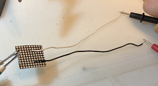 Here is one built sensor I cut squares of flexible protoboard (https://www.adafruit.com/product/3904)
flexible isn't really necessary, and less than ideal really, but it was inexpensive and easier to cut lots of small squares from than the regular stuff.
I have inexpensive reed switches, random amazon purchase. They work great, but are very fragile. Be sure to order extras.

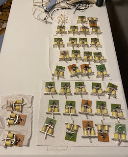
I meant to mount the sensor squares between the springs, but that didn't work well. I modified them by cutting slots to fit around the springs. Subsequent batches I made the slots before installing the switches which led to far less breakage.
If I were doing this again from scratch, I would remove all the pedals - the springs go with them, and be able to mount the sensors more easily to line up exactly with the top of the bottom rail there.
You can see the screws I set into the bottoms of the pedals - the magnets are just stuck to them. You can also see how in my haste I totally messed up positioning some of them. They were fixed later, it was a pain. Remind me to be more meticulous next time.
Except for the wonky implementation, this works - the screws can adjust the magnet position up or down to get the note to sound at the right place and when the felt gets replaced at some point, I can reposition them without redoing everything. These are 6mmx2mm magnets advertised as craft/fridge magnets. They were 6 bucks for 20 - I ordered one set to test them out, then went ahead and got enough for the project.

One wire connecting to each sensor goes to the ground bus - I used 1/4" copper tape which was easy-peasy and is working well so far. I covered the whole strip with a long piece of electrical tape. I cut and numbered graduated wires to connect the other sensor lead to the electronic system. I could have saved myself a wire solder and premeasured the inputs but this is how I did it. I have a little extra wire on each in case of emergencies, coiled up out of the way.
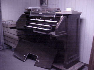
Here I hooked it up to Hauptwerk along with my digital piano to try it out. The table really doesn't work, it can't position the manual in the correct relation to the pedal, so it is hard on my back to play, but it was good enough to confirm it works :)

I did not get a photo of the electronics - right now it is just sort of hanging off the board, I want to make sure everything is in it's happy place before I commit to screwing it down.
I uploaded the code to github, https://github.com/lizny/OrganMIDIScanner
It has notes on what components are used. I'll have to owe a nicely drawn schematic and a photo. The manuals will use the exact same system, but with 4 expander chips instead of 2, so I'll have another chance then.
Next...
It's been a few weeks, during which there was confusion and missteps, but I'm on a roll now. I had grief with the Hall sensors, I think I fried a few but I have them under control now. In the flurry of this, I decided to use reed switches in the pedals, I won't get velocity sensing but if that annoys me enough I can swap them in later.
There was a bit of faffing around figuring out an approach, but here is what I wound up with that works:

flexible isn't really necessary, and less than ideal really, but it was inexpensive and easier to cut lots of small squares from than the regular stuff.
I have inexpensive reed switches, random amazon purchase. They work great, but are very fragile. Be sure to order extras.

I meant to mount the sensor squares between the springs, but that didn't work well. I modified them by cutting slots to fit around the springs. Subsequent batches I made the slots before installing the switches which led to far less breakage.
If I were doing this again from scratch, I would remove all the pedals - the springs go with them, and be able to mount the sensors more easily to line up exactly with the top of the bottom rail there.
You can see the screws I set into the bottoms of the pedals - the magnets are just stuck to them. You can also see how in my haste I totally messed up positioning some of them. They were fixed later, it was a pain. Remind me to be more meticulous next time.
Except for the wonky implementation, this works - the screws can adjust the magnet position up or down to get the note to sound at the right place and when the felt gets replaced at some point, I can reposition them without redoing everything. These are 6mmx2mm magnets advertised as craft/fridge magnets. They were 6 bucks for 20 - I ordered one set to test them out, then went ahead and got enough for the project.

One wire connecting to each sensor goes to the ground bus - I used 1/4" copper tape which was easy-peasy and is working well so far. I covered the whole strip with a long piece of electrical tape. I cut and numbered graduated wires to connect the other sensor lead to the electronic system. I could have saved myself a wire solder and premeasured the inputs but this is how I did it. I have a little extra wire on each in case of emergencies, coiled up out of the way.
Here I hooked it up to Hauptwerk along with my digital piano to try it out. The table really doesn't work, it can't position the manual in the correct relation to the pedal, so it is hard on my back to play, but it was good enough to confirm it works :)

I did not get a photo of the electronics - right now it is just sort of hanging off the board, I want to make sure everything is in it's happy place before I commit to screwing it down.
I uploaded the code to github, https://github.com/lizny/OrganMIDIScanner
It has notes on what components are used. I'll have to owe a nicely drawn schematic and a photo. The manuals will use the exact same system, but with 4 expander chips instead of 2, so I'll have another chance then.
Next...

Comments
Post a Comment